62
| WORLD FERTILIZER |
NOVEMBER 2016
in the catalyst’s optimum temperature range. This is
typically 350 – 450˚C for HTS catalysts and around
200 – 300˚C for LST catalysts.
3
In an energy-efficient ammonia plant, the excess heat
from the shift reaction is used to generate steam for
other parts of the plant. Since steam with a higher
temperature and pressure is more valuable as a heat
source, heat exchangers with close temperate approach
are preferred when optimising energy usage in the plant.
Fully-welded plate heat exchangers of shell and plate
type offer a high heat transfer coefficient due to the
counter current operation and long thermal length, which
results in narrow temperature approaches for more
effective waste heat usage. In comparison, shell and tube
heat exchangers tend to be very long where outlet
temperatures overlap.
CO
2
removal
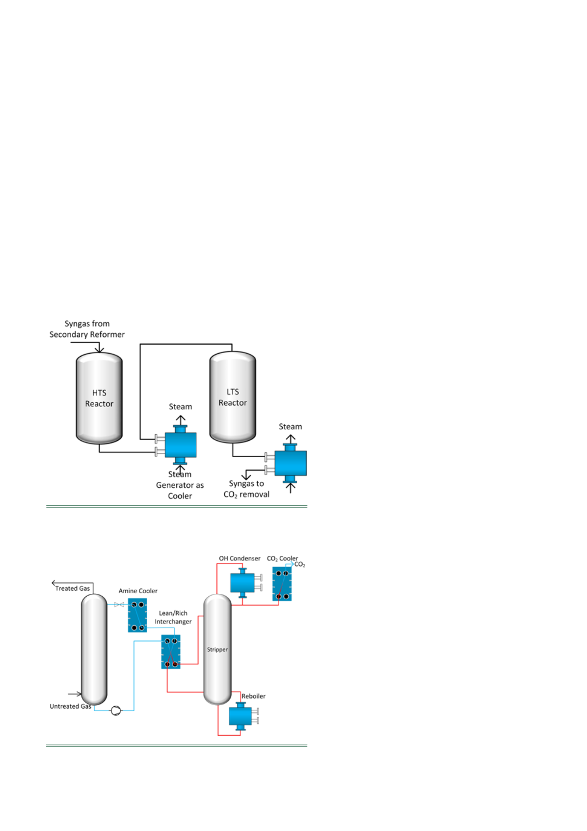
The most common process for removing remaining
carbon dioxide from the synthetic gas stream is by amine
gas treatment. This process removes the carbon dioxide
by absorption in an amine scrubber at low temperatures
and high pressures. The CO
2
rich amine exiting the
scrubber column is then regenerated in a stripper column
at high temperatures and low pressures. For this process,
all heat exchange duties can be done with plate heat
exchangers.
The cold, rich amine from the absorber is preheated
with the hot, lean amine from the stripper. The energy
efficiency of the amine process depends heavily on having
a close temperature approach in the lean/rich amine
interchanger, since this will recycle more of the heat that is
added to the stripper column by the reboiler. As plate heat
exchangers offer outstanding approach temperatures
compared to other heat exchanger types, they are the
preferred choice for rich/lean amine interchangers in an
efficient amine process. It is recommended to use a
gasketed plate and frame heat exchanger with long plates
and gaskets suitable for the specific amine for this
position.
For the reboiler and overhead condenser positions on
the stripper, an appropriate heat exchanger is a welded
plate heat exchanger with round plates, or the so-called
shell and plate heat exchangers. A shell and plate
reboiler can be designed for operation with a
circulating pump and as a thermosiphon because of the
short plates and large shell side nozzles giving a very
low pressure drop.
Using circular plates eliminates the weak corner
welds found on welded plate heat exchangers with
square shaped plates. The round plate evenly
distributes any load over the welded plate edge,
thereby assuring longevity and resistance to
mechanical fatigue due to temperature or pressure
variations.
The cooler for the CO
2
stream from the stripper
should preferably be a gasketed plate and frame heat
exchanger. If the ammonia plant is cooled with an
open cooling water circuit then there could be an
increased risk for high fouling rates on the cooling
water side. This should be prevented by designing the
heat exchanger with high channel velocity and shear
stress to prevent calcium carbonate or calcium
phosphate from the water depositing on the heat
transfer surfaces.
It is important to keep in mind that fouling rates in
amine heat exchangers are not only dependent on the
specific heat exchanger design but also on the purity of
the amine solution. An amine solution that is
contaminated by heat stable salts, injection chemicals
or hydrocarbons from upstream in the process could
cause fouling problems in amine plants' heat exchangers
(especially in amine reboiler and lean/rich
interchanger). The purity of the amine solution should
therefore be carefully monitored when preventing
fouling in the amine heat exchangers.
4
Heat exchangers for gas cooling are generally a
common position in many parts of the ammonia plant.
This application is ideal for welded plate heat
exchangers and especially the shell and plate type with
high-pressure resistance. This heat exchanger can have a
much larger nozzle on the shell side than on the plate
Figure 3.
Amine process for CO
2
removal with plate heat
exchanger positions.
Figure 2.
Water-gas shift reactors with shell and plate heat
exchangers for steam production.


