52
| WORLD FERTILIZER |
NOVEMBER 2016
CO
2
’s miscible properties with oil to enable it to flow easier,
became the first major application area for IGCs. It is now the
largest supercritical CO
2
application area, requiring more than
100 million short tpy of the gas.
It did not take long for IGC technology to crossover into
urea production, which consumes roughly one-tenth of the
amount of supercritical CO
2
used in EOR. In the last decade,
several fertilizer plants have switched over to IGCs.
Overview of IGC design
Integral gear technology is based around a central (integral)
gear box, inside which a main bull gear drives a number of
separate pinions. These pinions supply rotational power to
compression stages that are paired sequentially into stage
groups of two (Figure 1).
Integral gearing makes it possible to apply optimal speeds
to each two-stage group during the aerodynamic design
process. The best rotational speed for each stage is
determined by the rotor and aerodynamic properties of the
impeller, diffuser and volute – the parts of the machine that
compress the gas. This speed is translated into the gear ratio
between the bull gear and the corresponding pinion for its
stage group.
This stage optimisation is not possible on a single-shaft
machine, where all of the stages are arranged in one, or
sometimes two, housings and are run off the main shaft at
the same speed (Figure 2). Here, each stage speed is set by the
rotational speed of the shaft and a compromise is struck to
bring as many stages as close to their respective optimal
speeds as possible.
Stage speed optimisation
When comparing an 8-stage integrally-geared compressor to
a reference 12-stage single-shaft compressor under the same
operating conditions, one sees that the IGC’s individual
stage-group shaft speeds vary from as much as 87% faster to
about 10% slower than the constant 20 000 rpm of the
single-shaft design compressor (Table 1).
The ability to individually select stage-grouping speeds
that are best matched to the compressor-stage aerodynamics
is one of the primary factors to improve efficiency for
integrally-geared compressor.
Intercooling
In addition to stage speed optimisation, the integral gear
design also supports intercooling, which is possible between
all of the stages. Intercooling is essential for high isothermal
efficiency – a measurement of the deviation of the actual
compression process from an ideal, theoretical compression
process.
In the 8-stage IGC, intercooling is applied on stages 1
through to 5. The final, high-pressure stages, 6 to 8,
(compressing from 70 to 200 bar) are not intercooled. This
creates a tolerance zone above the gas’ condensation point:
CO
2
turns supercritical over 73.8 bar at 31˚C.
By comparison, intercooling is more complicated, bulky
and costly in a single-shaft design, requiring that the housing
is divided into sections.
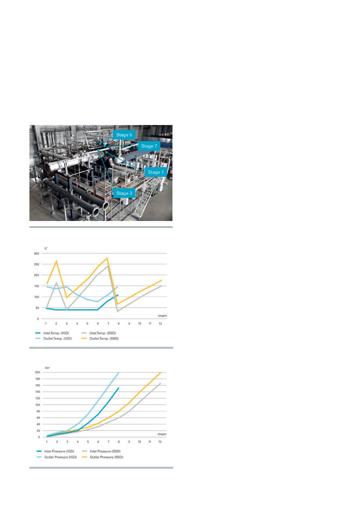
To simulate the feasibility of the aerodynamic design for a
single-shaft machine, intercooling after stage 2 and stage 7
was modelled. Notice that the inlet temperatures of the
integrally-geared compressor remain below those of the
single-shaft for all stages except stage 8, which is comparable
to stage 12 of the SSD (Figure 4).
Power requirements and efficiency
The higher discharge temperatures of the single-shaft
compressor along with its additional stages at high pressures
(in this case, four additional stages) must be considered when
selecting housing-wall materials and determining their
thicknesses. This creates a noticeable impact on compressor
costs, giving the integrally-geared design a considerable plus
in this respect.
Figure 4.
Temperature per stage in ˚C.
Figure 5.
Pressure per stage in bar.
Figure 3.
8-stage compressor in package assembly.


