NOVEMBER 2016
| WORLD FERTILIZER |
57
and a second temperature control loop, but this is
counterbalanced by the benefits described above. Furthermore,
this type of control philosophy can react much faster in case of
process disturbances since there are no large volumes/masses
between the temperature sensors and the bypass actuators, and
both control loops are almost independent of each other.
Process gas cooler design
The requirement for low capital costs also impacts the design of
the PGC. Design margins are squeezed out and consequently a
cost-effective design is achieved, but the PGC is thermally and
mechanically high loaded. All major design parameters can be
seen as pieces of a puzzle that have to perfectly fit in order to
achieve a reliable PGC design. Changing certain design parameters
has to be done carefully, since one parameter affects the other
factors. This becomes more important for designs that are close
to their limit. If the design variables are misaligned, there may not
necessarily be a sudden failure during first start-up of the PGC,
but the life time will be reduced through multiple repairs, worse
reliability and availability of the PGC, and the overall waste heat
boiler package, henceforth reducing the availability of the total
complex and leading to a higher probability of high financial
losses.
Besides the thermal design goals, a mechanical design target
is a tube sheet with low mechanical and thermal loading. The
tube sheet is the heart of the process gas cooler; it separates the
two pressure levels and media streams, and is equipped with the
process tubes. Two basic and well-known principles of tube sheet
technologies exist, namely the stiffened and flexible tube sheet.
The stiffened tube sheet can be distinguished in a thick stiffen
tube sheet and a thin tube sheet with stiffener plates. For those
concepts, each specialised vendor owns its technology details.
Since the process parameters and boundary conditions are
preconditions, the PGC should be designed in a way to reduce
the impact of the process parameters on the tube sheet,
tube-to-tube sheet welds and the mechanical structure. In
general, thin tube sheets (flexible as well as thin with stiffener
plates) are beneficial since they have lower thermal stresses
compared to thick and stiffened tube sheets.
Two examples of the overall design puzzle will be discussed
more in detail in the following. In principal, the dependency of
the design parameters is valid for all tube sheet technologies, but,
depending on the tube sheet design, the situation gets more
serious.
The first area of conflict between commercial and technical
targets is the tube pitch at a given tube diameter and tube
number. A small tube pitch reduces the area at the tube sheet,
where the pressure forces by process gas and water/steam can be
applied. This consequently leads to lower mechanical loads by
the pressure forces and therefore is more suitable for a thinner
tube sheet and provides a positive cost effect. In addition, a
smaller tube pitch leads to a smaller tube field diameter. This
leads to a smaller PGC diameter and in consequence to a shell
with lower wall thickness. In total, the PGC weight is lower, which
enables lower costs for the PGC. Also transportation from
manufacturer to place of operation becomes less of a challenge.
From this point of view only, a designer should choose the
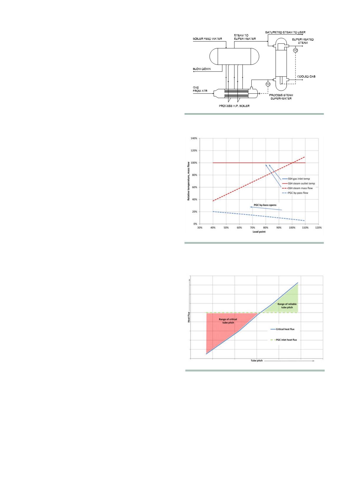
smallest tube pitch. But looking into a second function of the
tube pitch changes the assessment. The tube pitch creates
channels between the tubes in which the steam bubbles flow,
which arise at the outer tube surface. From a fluid dynamic point
of view, a small tube pitch constrains the flow area that the
steam bubbles have to pass. This increases the risk of steam
bubbles accumulating instead of flowing and consequently
drying out and, in turn, creating local over-heating. This has to be
seen in conjunction with the PGC inlet heat flux, which depends
on the process parameters and the tube diameter. To avoid local
dry out in the tube bundle, the heat flux, by design, should be
below the critical heat flux, which indicates the limit for local
dry out. In principle, the critical heat flux depends on the
pressure level of the water/steam side, tube geometry and
Figure 3.
P&ID of PGC package with two temperature
controls (concept 2).
Figure 4.
Temperature and bypass mass flow over
the operational range for two temperature controls
(concept 2).
Figure 5.
Variation of tube pitch at constant tube
geometry and number.


