30
| WORLD FERTILIZER |
NOVEMBER 2016
Any oversized material is crushed and returned to the
granulator as seeding particles together with any undersized
grains. The specification-grade product is sent to storage after final
cooling in either a fluidised bed or a bulk flow cooler operated
with cooling water.
Urea dust entrained in the air from the granulator, the fluid
bed coolers and various dedusting points is recovered in a
scrubbing system.
The UFT fluid bed technology is renowned as a successful
granulation process, featuring the following highlights:
n
n
Flexibility
: its outstanding flexibility virtually allows all
requested product size distributions from an average diameter
of 2 – 8 mm. Adjustable turndown ratios with less than 50%
of the nominal capacity are feasible.
n
n
On-stream time
: the inherent reliability of the process is
largely due to the fact that the granulators have no moving
parts.
n
n
Emissions
: due to UFT’s exclusive cooperation with Kimre an
even more cost-effective scrubbing technology can be used
to recover the valuable product. The horizontal type
scrubbers allow customised configurations with specially
designed scrubbing pads for very high separation efficiency
and low pressure drop to meet the most stringent
environmental requirements.
n
n
Large single-train capacities
: the world’s largest granulation
plant has a capacity of 3850 tpd and is using UFT technology.
Emissions
There are only a few ammonia emission sources within the urea
plant, namely the absorbers in the solution part and the vent
stack in the granulation part, which also emits urea dust.
The granulation off-gases used for the fluidised bed in the
granulator and for product cooling contain a high amount of urea
dust and some ammonia carried over from the urea melt. To
comply with the guaranteed emission figures and the
environmental legislation, an abatement system has to be applied.
While previously it was possible to use a simple Joy type scrubber,
a much more sophisticated and efficient solution is used within
modern plants. Today, the dust and ammonia emissions are limited
to 50 mg/Nm³ by World Bank standards on which most of the
local emission laws are based. To achieve this, thyssenkrupp uses
scrubbers that are equipped with different, dedicated stages. In
the first stages of the scrubber, the dust is removed and solved
into the scrubbing solution. This scrubbing solution containing up
to 50Wt% of urea is sent back to the urea synthesis process. This
ensures the produced urea stays in the process and no
unnecessary nitrogen containing effluent is sent to the wastewater
system.
Additional scrubbing stages can be added downstream the
dust stage. If the authorities require reductions to the plant's
ammonia emissions, thyssenkrupp is able to add a second
section for ammonia abatement. Here the off-gases are washed
with a low pH scrubbing solution to absorb the ammonia
contained in the off-gas. thyssenkrupp’s common practice in
fertilizer complexes with an attached nitric acid and UAN plant
is the use of diluted nitric acid, as the produced ammonium
nitrate can be used in the UAN process. To lower the ammonia
emission further, the off-gases from the synthesis section are
also sent to an acidic scrubber. Depending on the design, size
and acid consumption of the scrubbers, the ammonia
emissions from the whole urea plant can be lowered to
minimal amounts.
All liquid emissions containing urea or ammonia either from
the scrubbing section or other liquid sources, such as process
drains, are collected within the plant and sent back into the
process. The only liquid effluent is purified process condensate
containing about 1 ppm of ammonia and urea as a byproduct of
the urea formation reaction. This water can be used as feed for the
demineralisation unit or as makeup water for the cooling tower.
To reduce the emissions of the synthesis section in case of an
emergency, thyssenkrupp uses three steps to lower the impact of
the main synthesis trip:
n
n
Avoidance
: to avoid the opening of the synthesis safety
valves, thyssenkrupp monitors the system pressure via three
SIL certificated pressure switches. If two indicate an
increased process pressure, the synthesis is blocked in and
all pumps are isolated from the system. The process can be
restarted safely within a few hours or up to a few days
without draining the synthesis loop.
n
n
Reduction
: high-capacity safety valves, such as the one on the
synthesis or on the LP section, are equipped with additional
safety valves with a lower capacity and a slightly lower set
pressure. This cascade ensures that, in case of a minor defect
or in case of mal-operation, the smaller safety valve opens
and only a limited amount of process medium is released. If
the pressure continues to rise, the second, high-capacity valve
opens.
n
n
Collection
: if necessary or requested by the client, the safety
valves releasing to the atmosphere can be routed to an
additional catch pot, where the liquid phase is separated from
the gas emissions. The liquids are collected and can be sent
into the process when the plant operation is back to stable
conditions.
thyssenkrupp owns licences for ammonia plants, nitric acid
plants and UAN plants. To complete a fertilizer complex,
thyssenkrupp is able to build a urea formaldehyde plant (used as
anti-caking agent in the granulation) under licence and an
AdBlue®/DEF mixing facility.
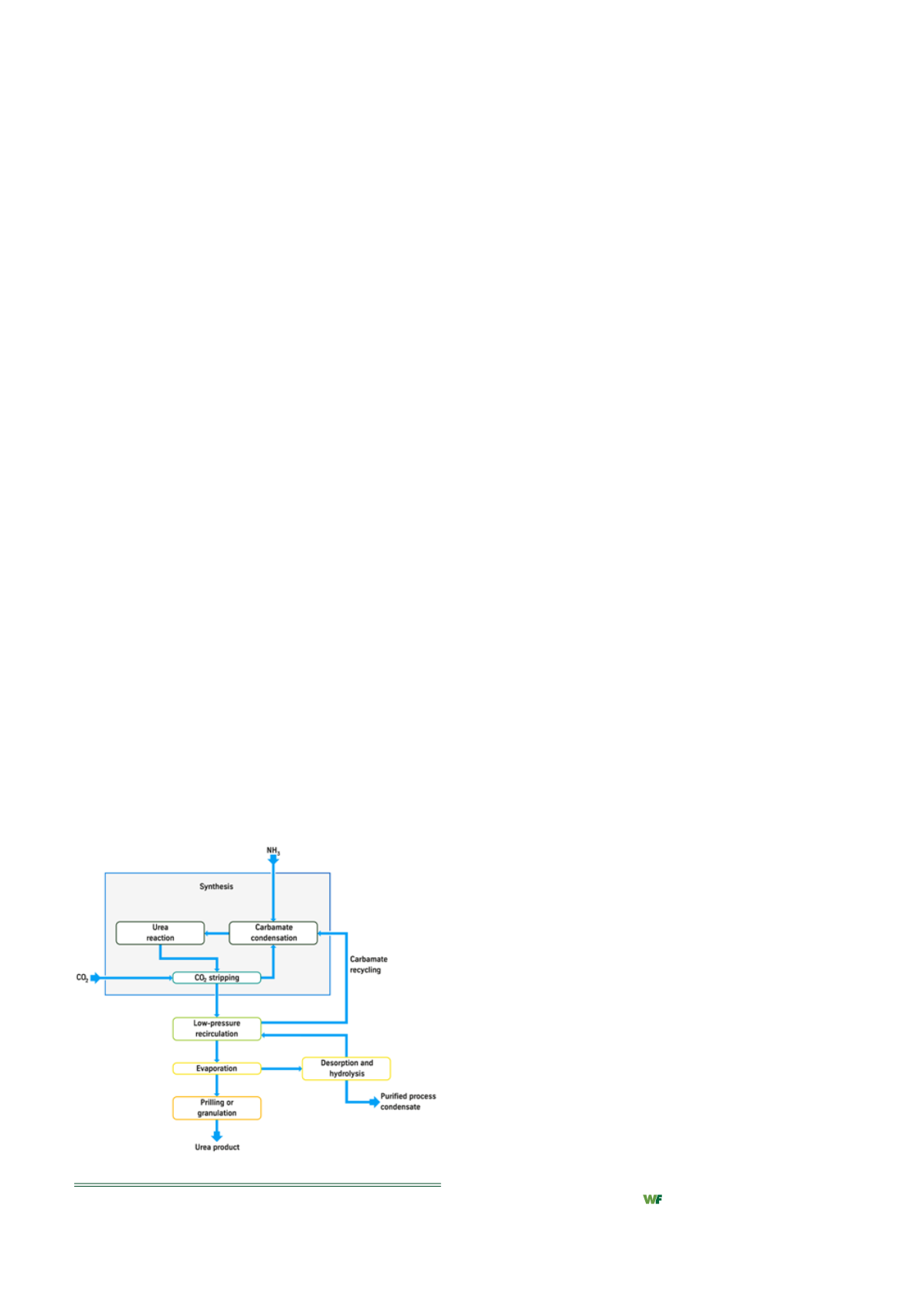
Figure 3.
Block diagram of the CO
2
stripping process.


