88
| WORLD FERTILIZER |
NOVEMBER 2016
low-efficiency bubbling-type combination scrubber. The vent
gas was bubbled through the liquid section, where ammonia
and urea were removed. The removal efficiency of both
ammonia and urea was very low contact time, and low
turbulence limited urea particulate removal and vapour
Figure 10.
Scrubber retrofit in progress.
Figure 11.
Completed scrubber retrofit.
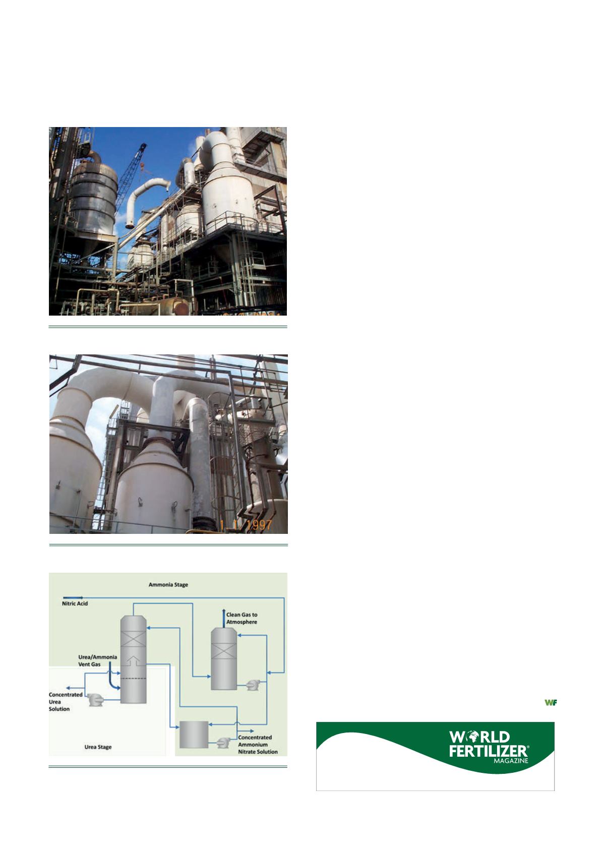
Figure 12.
Combined urea-ammonia removal and product
recovery with acid.
pressure at the high temperature reduced the ammonia removal
efficiency.
Macrotek was contracted to re-design the overall system
and improve removal efficiency for both urea and ammonia.
The low-efficiency, low-tech bubbling scrubber was retrofitted
to a two-staged plate and packed column absorber (Figure 9).
The first stage combined with upgraded controls resulted in a
significant improvement of urea collection and recovery. In
addition, the end-product was a more concentrated solution,
resulting in better product re-use and lower evaporator duty.
The ammonia removal retrofit, however, was more
challenging. The most common approach to remove ammonia
(particularly at elevated temperatures) is to use acid (most
commonly sulfuric or nitric). Due to limited acid availability and
cost, using acid for neutralisation was not a viable option.
Macrotek initiated an extensive evaluation of possible
options. After investigating modelling and design configurations,
the concept of using CO
2
to maintain pH and generate usable
byproduct was implemented. In addition, CO
2
vented to the
atmosphere was reduced (Figures 10 and 11).
Combined urea and ammonia removal using acid
A large fertilizer facility in Western Canada required a system
upgrade to improve ammonia removal in order to meet new
and more stringent regulations. The original installation
included the Macrotek MJ plate-tray scrubber for combined
urea and ammonia removal. The combination resulted in a
mixed byproduct and a more difficult process to re-use the
byproduct.
Macrotek was contracted to improve removal efficiency
and enhance byproduct recovery. A detailed evaluation and
process design was conducted to develop a design concept
and accomplish these objectives. It was common practice in
earlier plants to combine many vent sources and direct all to a
common scrubber for treatment. In this case, the large vent
source was mainly urea and several of the smaller streams were
mainly ammonia. The approach was to separate these sources
and to use the plate-tray scrubber for the urea and to design a
dedicated acid scrubber for the ammonia sources (Figure 12).
The final result was that emission levels for both ammonia and
urea were improved, reusable byproducts were generated and
optimum use of byproducts was realised (separate
concentrated urea and ammonium salt); all objectives were
achieved.
Conclusion
Different control technologies are available for the control of
urea and ammonia from various vent sources. Macrotek’s
approach is to evaluate all considerations and custom design a
fit-for-purpose system that will reduce emissions to the most
stringent levels and generate a usable byproduct. In most cases,
added benefit is realised by using dilute wastewater streams as
makeup water. This reduces the load to the wastewater plant or
evaporator while generating a concentrated, usable product.
Register to
receive a regular copy


