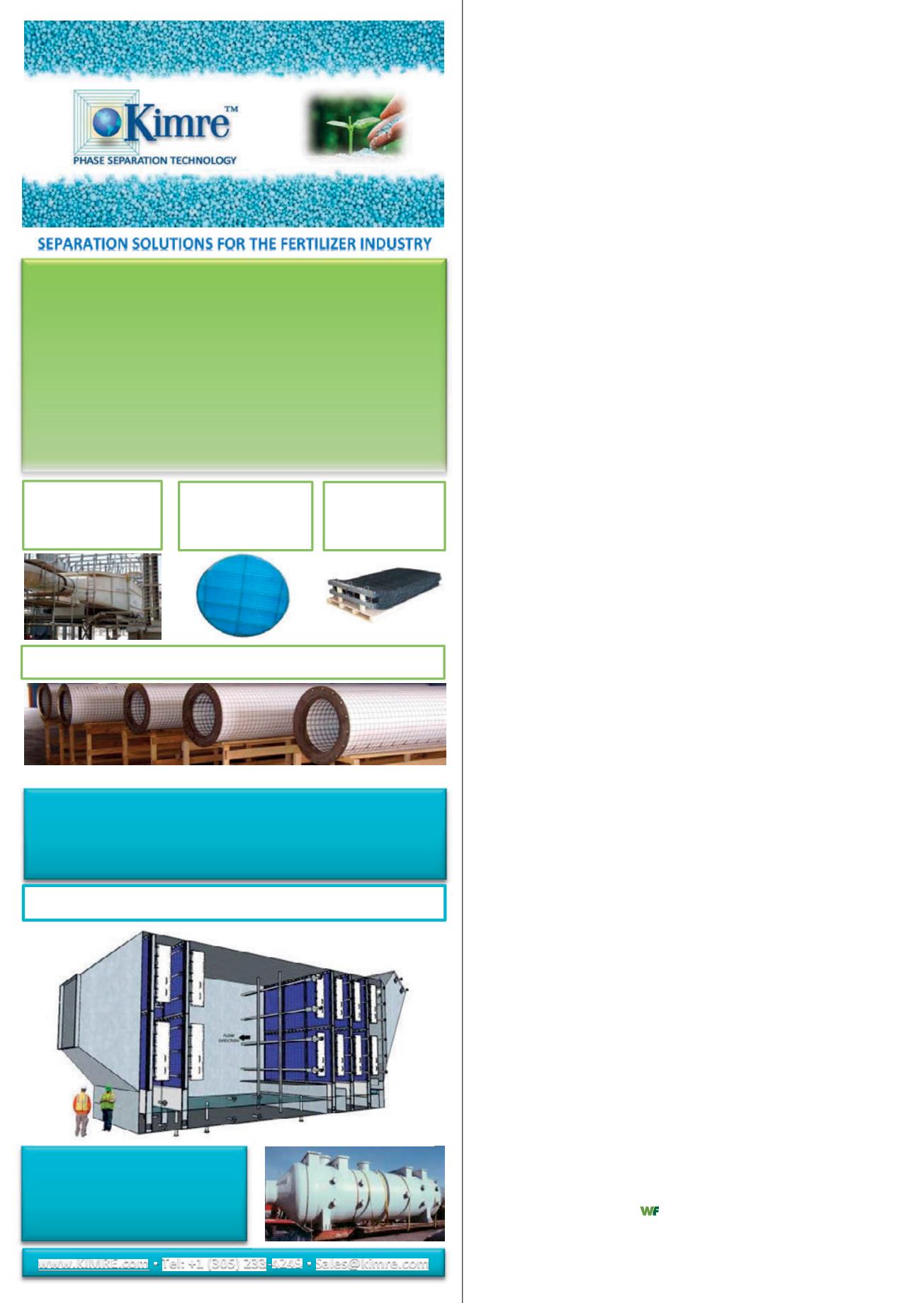
PHOSPHATE/FERTILIZER/PHOSPHORIC ACID
PHOSPHORIC ACID PRODUCTION:
Fume Scrubbers ▪ FSA Recovery ▪ Vacuum Cooler Scrubbers ▪ Evaporators
AMMONIUM PHOSPHATE & NPK PRODUCTION
Fluoride particulate & ammonia emissions in MAP, DAP, & NPK Plants
ANIMAL FEED INGREDIENTS PRODUCTION
SUPER PHOSPHATE PRODUCTION
SSP & TSP plants fume scrubbers ▪ FSA Recovery ▪ Odor Control Scrubbing
SULFURIC ACID PRODUCTION
Drying and Absorption Tower ▪ Fuel gas cleaning
ROCK PRODUCTION
NITROGENOUS FERTILIZER/UREA
AIR POLLUTION & DUST CONTROL SYSTEMS FOR:
UREA PRILLING & GRANULATION
CAN GRANULATION
AMMONIUM NITRATE PRILLING & GRANULATION
KIMRE SXF™
SEMI-CROSS FLOW
SCRUBBER
B-GON® MIST
ELIMINATORS &
KON-TANE® TOWER
PACKINGMEDIA
BATTEN BAR™
MEDIA HOLDING
SYSTEM
KIMRE™ FIBER BED COALESCING FILTERS
AEROSEP® MULTI-STAGE AEROSOL SEPARATION SYSTEM
• Highest collection efficiency
• Low pressure drops
• Any size and configuration
• Excellent fouling resistance
• Cleanable & reusable media
• Extended service life for harsh services
▪ Tel: +1 (305) 233-4249 ▪
For some applications, it is advisable to conduct a parallel
installation of a safety valve and rupture disc, in case of a rapid
and unacceptable pressure increase, both units will trigger and
perform a parallel relief.
A rupture disc is therefore not a common technical supply
item, but rather the key safety element that provides a decisive
contribution to the overall plant availability with or in addition
to safety valves. This is not just limited to the oil and gas
industry but applies where pressure and vacuum are present.
To protect various elements of fertilizer production plants,
rupture discs are a key element for a safe plant operation. Using
the right rupture discs reduces downtime, enhances product
quality and lowers operating costs. As choosing the right rupture
disc depends on various parameters, choosing the right partner
is mandatory.
Several widely used standards, such as EN ISO 4126-3 and the
German AD2000 Merkblatt A1 and A2, specify certain
requirements for a combination of a RD and a SV. To prevent any
functional impairments of a SV by the RD, it must be ensured
that when the RD responds, there is no fragmentation of parts.
Alternatively, suitable design measures or catching contours
must be put in place to ensure that the SV cannot be rendered
ineffective by fragments. The distance between the RD and the
SV must be as small as possible to reduce any pressure drop
caused by the pipe. Yet the distance between the RD and the SV
also must be big enough to warrant the safe and reliable
opening of the rupture device. The RD and the pipe must be
configured in such a way that the overall pressure drop towards
the entry point of the SV is less than 3% of its response pressure.
The various standards specify a variety of options for dealing
with pressure drop. According to AD2000-Merkblatt A1, the way
to deal with pressure drop on any parts of the rupture element
that are still in the clamping device after a response has taken
place […] is to ensure that the cross section of the clamping
device meets the following condition and that the rupture
element is mounted directly in front of the SV:
Ageom
x α >
1.5
x
A0
x αw
The area Ageom specifies the geometric cross section of the
rupture element. This also covers any restrictions of the cross
section, e.g. caused by cutting devices or non-opening vacuum
supports. The area A0, on the other hand, specifies the
narrowest cross-sectional area of flow within the SV. The
discharge coefficients
α
of the RD and
αw
of the SV are also
considered in the equation. According to the standards ASME
section VIII, Div. 1, and DIN EN ISO 4126-3, it is also possible to
apply a correction factor of 0.9 to reduce the discharge
behaviour of the SV ‘artificially’. Alternatively, a single discharge
coefficient for the combination of a RD and a SV may be
specified by performing an additional testing.
Furthermore, when combining a RD and a SV, a device must
be in place to detect or prevent any change of pressure in the
space between the two safety devices. Any possible
back-pressure would influence the burst pressure of the RD and
would prevent the reliable functioning of the combination. A
relief valve with an alarm pressure switch connected to it
simultaneously signals any improper over-pressure. This is a
proven solution that prevents and detects improper pressure
build-up in the space between the two safety devices. If the RD
responds, the relief valve closes and the pressure switch signals
that the RD has responded.


