NOVEMBER 2016
| WORLD FERTILIZER |
117
to increase plant reliability. A steam turbine acts as the main driver
and an electric motor functions as the auxiliary driver; these are
connected to the fan shaft
ends. To allow for single-driver
operation, two over-running clutches are provided between the
fan shaft and the drivers. When a failure in the steam turbine
occurs, the electric motor starts at no load and engages the
decelerating fan.
Steam is generally available for this process and hence a steam
turbine is used as the main driver through the gearbox during
normal operation.
However, when steam is not available at plant start-up, or
when a turbine trips, the fan must be kept in operation in order
to safeguard the process and avoid any sudden plant
shut-downs. For this reason, an auxiliary electric motor driver is
connected to the other shaft end. To avoid driving the idle driver
when the main or auxiliary driver is driving the fan unit, two
over-running clutches on both fan ends are generally used to
engage and disengage the idle driver automatically. A typical
arrangement is shown in Figure 1.
Normal operation
As per API requirements, an overdesign margin of 15% is required
on fan flow rates and a 32%margin on the fan pressure at the rated
point.
This means the normal fan operating point is reached
when:
n
The fan is at full fan speed with a partial regulating damper
opening under motor operation.
n
The fan is at reduced speed with a full regulating damper
opening under steam turbine operation, in order to save
steam consumption.
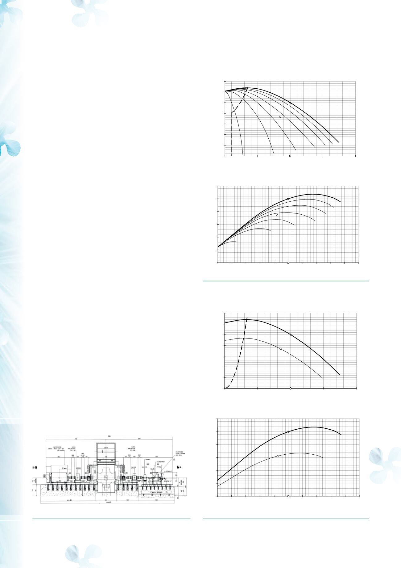
Typical operating curves for the normal point are shown in
Figures 2 and 3.
Turbine trip
In the case of steam turbine failure, the DCS detects the fault and
automatically switches to the electric motor within the shortest
possible time to avoid tripping the reformer.
The typical sequence upon fault detection is as follows:
n
The steam inlet valve (trip valve) upstream of the turbine is
closed and a related trip signal is sent to the DCS.
n
The fan begins to slow down due to the lack of motive power
from the main driver. Capacity and pressure reduce
proportionally to speed.
n
The auxiliary motor drive is activated by the DCS and
increases the speed at no load (clutch disconnected), while
the fan slows down.
100%
-15°
-30°
-45°
-60°
-75°
-85°
Rated
Normal
0%
20%
40%
60%
80%
100%
120%
140%
0%
50%
100%
150%
200%
Pressure [%]
Flow Rate [%]
FLOW RATE - TOTAL PRESSURE
0°
-15°
-30°
-45°
-60°
-75°
-85°
Rated
Normal
0%
20%
40%
60%
80%
100%
120%
0% 20% 40% 60% 80% 100% 120% 140% 160% 180% 200%
Power [%]
Flow Rate [%]
FLOW RATE - SHAFT POWER
Non operability
area
100%
85%
Rated
Normal
0%
20%
40%
60%
80%
100%
120%
140%
0%
50%
100%
150%
200%
Pressure [%]
Flow Rate [%]
FLOW RATE - TOTAL PRESSURE
100%
85%
Rated
Normal
0%
20%
40%
60%
80%
100%
120%
0% 20% 40% 60% 80% 100% 120% 140% 160% 180% 200%
Power [%]
Flow Rate [%]
FLOW RATE - SHAFT POWER
Non operability
area
Figure 1.
Typical machine arrangement.
Figure 2.
Fan performance curves.
Figure 3.
Fan performance curves.


